I’m fresh back at work for 2023, and feeling the energy as people set their mind to the year ahead. I’m quickly hearing a theme around team communication and connection, as the leaders in my network refine their approaches to hybrid work and distributed teams.
I’m hearing leaders planning to start writing a weekly note, start a monthly newsletter, or refresh their town halls. These are good, important plans; it’s foundational for leaders to consistently provide engaging and timely insights.
But I don’t think these particular plans should be advertised.
—
The first weekly note will be good, but not great, because it’s the first. Or it’ll be delayed under the pressure of waiting until it’s great before starting.
The second one will be light on content, as it turns out that not much new has happened yet. Maybe we should have done this fortnightly instead? Did I put too much in the first one? I can’t break the pattern this early! You use some fillers, and the content quality takes a dip instead.
Some weeks will be great. Some will be a chore. Some will be a complete overload of comms from other teams or functions, and then you’re throwing more content on the fire.
Is this even my communication style? Does this work for me as a leader? Is it working for my team?
—
Having a structured communication approach is important.
Having a content plan, and a regular rhythm is really useful.
But your audience need to know the content – not the plan.
Don’t start with a commitment. Just publish your first one. Then your second one. Then your third. And then you have a trend.
You’ll find your rhythm. You’ll find the weeks that it makes sense to post something, or the ones where it makes sense to wait a week. You’ll find the day that works best. You’ll find the content that resonates. You’ll discover how the conversation plays out: how people engage, respond, challenge, or enquire.
People will work out if you’re posting most weeks, about monthly, or each sprint. Or they won’t care, and it doesn’t matter. What matters more is the actual communication.
Keep space to change your priorities and iterate your plan. Some weeks, your priority as a leader won’t be communication or engagement, and that’s ok. If it doesn’t stick, you can just stop; you don’t have to announce an intent to stop / cancel / give up.
Start the year talking about what matters. There should be a million things more important and more engaging to start with than “I’m going to start a weekly update”.
—
Some practical tips:
Know your reason, write the content
People often transpose their reason for writing into the opening lines. They’re sitting down to write their first weekly note, so they write about writing a weekly note.
“Hi team. This year I’m going to start writing a weekly note, so here’s the first! These notes will include regular updates on our strategy, our plans, our performance, and other key messages that come up throughout the year.”
Know why you’re writing, but write about the bit that matters.
“Hi team. I’ve been reflecting on our strategy and plans. Here are the five areas that are top of mind for me, and why:”
It’s just an update
The subject line or title box can be another publishing papercut. I’m a fan of keeping it generic, and just using the format “[Team/Project/Group Name] Update”, like “Digitisation Update”. I find words like ‘newsletter’ a bit formal, and I think the starting focus should be on quality content over brand names.
Blank, 2, 3, 4
I’ve found it useful to number the updates once you get going. They help to softly demonstrate regularity, and make it easier for people to know if they missed one. When we were launching Telstra Purple, I started with “Purple Update”, then “Purple Update Vol. 2”, “Purple Update Vol. 3” and onwards. Suddenly a year had passed, and I found myself writing “Purple Update Vol. 23”.
If you’re posting to a platform like Teams, Yammer, or Slack, then you’ll be able to link to previous posts.
I like to include a little back link like this as the end of posts:
This makes it possible for people to join at any point, and still discover the recent history. They might be new to the team, back from holidays, or just taking a new interest. The process of quickly grabbing the link also gives me a prompt to compare back on what I said last, and make sure that I’m not repeating myself.
They’re the minutes from the “27th meeting of the General Conference on Weights and Measures”, published by the International Bureau of Weights and Measures. Skip to page 19 for English.
Resolution 1 is a slow start. It notes “the increasingly multidisciplinary nature of measurement in new or disruptive technologies, and the new requirements for metrology in digital technologies, sensor networks, and big data,” and sets up some working groups. That’s metrology – the scientific study of measurement – not meteorology.
Resolution 2 considers that while everybody is chasing digital transformation, our existing SI unit system (basically the metric system) isn’t going to cut it for much longer. Specifically, “maintaining and building confidence in the accuracy and global comparability of measurements will require the creation of a full digital representation of the SI, including robust, unambiguous, and machine-actionable representations of measurement units, values and uncertainties”.
Resolution 3 says the data scientists have been busy generating bigger and smaller numbers, using orders of magnitude in excess of 1024. The ol’ kilo/mega/giga prefixes are comparatively tiny these days. Unofficial new prefix names have taken hold, so we should probably make them official. Introducing: ronna/R (1027), ronto/r (10-27), quetta/Q (1030), and quecto/q (10-30).
Resolution 4 just casually starts to redefine time. Most countries run time based off UTC and a time zone offset. Every four years we throw in a bonus day to keep the calendar lined up with Earth’s orbit: a leap day. There’s a smaller effect that most people don’t know about though, and that’s the leap second. This exists because we currently have a rule that UTC must stay in agreement with another time system, known as UT1, which is based on the angular rotation of Earth. Whenever the Earth is approaching 0.9 seconds ahead, the UTC clock gets shoved forward by 1 second to catch up. This is enacted using a process defined by the International Telecommunication Union (what‽). It doesn’t happen on a regular schedule like every 4 years; it happens whenever the International Earth Rotation and Reference Systems Service says it needs to happen, which makes it a nightmare to plan for. It’s also really hard to do without crashing everything; few software packages expect to see 61 seconds in a minute. Google and Amazon achieve it in their cloud environments by “smearing” the extra second in over the course of a whole day. If that didn’t all sound hard enough already, here’s the real kicker: the Earth’s rotation is slowing down, and we might soon need to do our first ever negative leap second. What could possibly go wrong? The resolution is to buy ourselves time (boom-tish) by increasing the allowable variance, and to come up with a new model that will work for at least the next century. Whilst pragmatic, it’s a bit sad that computers are forcing us to disconnect our concepts of time and space.
Resolution 5 keeps up the pace on redefining time, by saying that our definition for a second isn’t good enough anymore either. In 1967, the second was defined as “the duration of 9 192 631 770 periods of the radiation corresponding to the transition between the two hyperfine levels of the ground state of the caesium 133 atom”. In 2018, they rearranged the math, but stuck with the underlying physics. Our measurement tools now far surpass the definition. The solution is: a competition! Competitors (countries) must bring their proposals to the next meeting (in 2026), so that a new definition can be adopted at the following meeting (in 2030). How many stakeholder alignment meetings do you think occur in the run-up to those‽
Resolution 6 is basically a recruitment drive for world domination, so that the metric system may provide global sanity. There were 48 member countries in 1999, and there are 64 now. The last time the US had a functioning government, their view was to provide no useful opinion, and leave metric adoption entirely to individual consumer choice.
Resolution 7 lays out the fees for countries to stay involved: €13m/yr.
What a fascinating document.
—
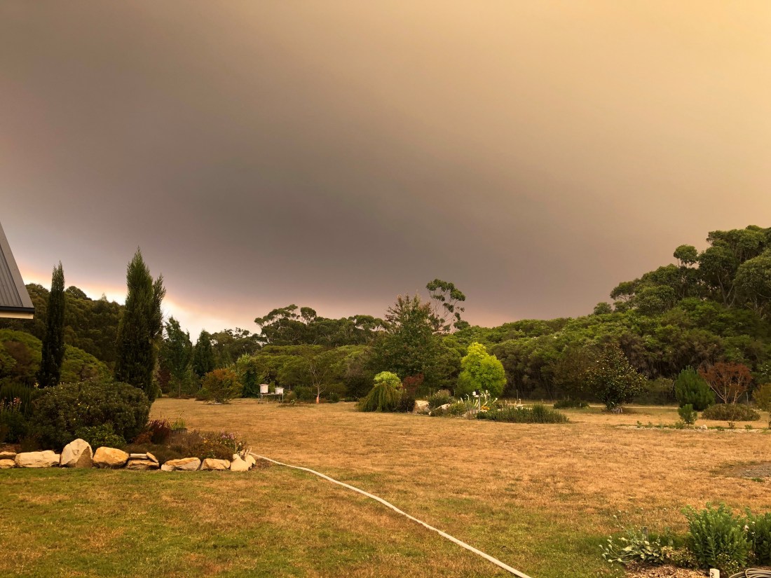
Header photo taken while we were camping somewhere along the Birdsville Track, in July 2021. The trees in the foreground are lit by our campfire.
I think about optimisation goals a lot. For me, that’s about being actively aware of what ‘great’ looks like, and what should be traded off to get there.
Every time we optimise towards a goal, other scenarios become suboptimal. We can’t simultaneously optimise for everything; the math just does not work. (My mental model here is grounded in the applied mathematics version of optimisation, and the definition of ‘suboptimal’ being ‘less than optimal’. Suboptimal doesn’t mean bad, it just means it’s not optimal).
Especially in a large organisations, I think it’s really important to focus on the optimisation goals. I choose to believe that people act with good intent, so if something seems weird or wrong to me, then my starting assumption is that their optimisation goal is different to mine. My first step is to identify what their goal is. If it’s optimised appropriately for the organisation, then I can be comfortable, even if I’m stuck in the suboptimal experience of something. The organisation here is the whole company; not any one function or team.
This approach helps me actively seek out organisational context, be confident that I’m delivering the broadest possible impact, and generally maintain a positive outlook throughout whatever I’m working on.
Without this approach, it’s easy to get trapped at everything just feeling suboptimal, which is a pretty unexciting place to be.
We’ve recently been learning more about the energy usage through our home in Melbourne, Australia. We’re still on the first lap around the sun with this house, so each month brings a new experience of how it behaves.
Whilst we chip away at draught sealing, and slower projects like insulation and window improvements, we wanted to at least optimise how we were using energy, and in particular, electricity.
Smart Meters – What We Have
All houses in Victoria have a smart meter, which constantly reports back intra-day usage data. This is then user-accessible via the chosen retailer.
It’s kind of interesting, because you don’t get a bill surprise six-weeks after you used the energy, but it’s not very granular. Reporting is in 30-minute blocks and delayed. This means you’re stuck looking at very high-level trends. It makes sense considering the volume of meter data that needs to get pushed around and aggregated between all the mesh-connected smart meters, but it’s not a great user experience.
We currently use Powershop, who expose both data export and a few visualisations, like this heatmap:
Screenshot of Powershop’s energy history heatmap visualisation
Smart Meters – What We Could Have
The smart meters deployed in Victoria also support local Zigbee connectivity.
That’s the same underlying protocol that other smart devices like Phillips Hue already use, which would make it excellent for surfacing local, real-time energy information directly into a home automation platform.
One intended use of the Zigbee capability is to support the connection of an in-home display, so that you can have something like this Rainforest EMU-2 sitting in a visible area of the home:
In-home displays (IHDs) are devices that give a visual indication of how much energy the home is using and what it is costing at any given time, using data transmitted from a smart meter or submeter. Most of us never go near our electricity meters, so we cannot easily see how quickly the registers or the numbers on the display are changing. Even if you could, it would still be difficult to work out how much electricity you are using, how much it is costing, and whether it is more or less than it was an hour, a week, or a year ago. If your home is on a time-of-use tariff, the display will help you to know exactly when one price period ends and the next one starts, which can be hard to remember.
IHDs can bring all this information inside your home, or onto your computer and smart phone, in a form that is easy to understand. The simplest IHDs indicate with coloured lights or symbols, whether you are in a high, medium or low price period, to help you decide whether to run high-load appliances such as vacuum cleaners. An IHD of this type needs to know only the clock time and time-of-use tariff schedule, which can be pre-programmed.
I don’t want a separate screen; I just want to get the data flowing into my home automation platform. There is a well-defined specification for the “ZigBee Smart Energy Profile 1.1”, and we already have a Zigbee ecosystem in the house.
The first thing I found was that the pairing process was the inverse of what I expected. I thought I would take our existing Zigbee coordinator, put it into pairing mode, and then somehow tell the smart meter to join. What I discovered was that the smart meter acts as a coordinator, and everything else gets added as a client. In retrospect, this does make some good sense: it means that people just need to add an in-home display, and not a separate hub in the middle.
The next thing I discovered is that the smart meter’s coordinator is centrally controlled. There’s no way to directly trigger a pairing process on it. This seems to be the global standard in how these devices work.
Specifically, it’s done via the energy distributor. For us, that’s Citipower/Powercor, who provide distribution for ~1.2 million Victorian homes.
Regardless of which retailer you’re using, you can establish an account directly on their myEnergy portal. (If you’re on a different Victorian distribution network, here’s a handy list of equivalent portals.)
A Home Area Network (HAN) device, such as an In-home display, can be used to wirelessly access near real-time and historical electricity consumption information directly from your meter (interval ‘smart meter’). myEnergy provides you access to your meter to authorise the connection of one or more HAN devices. Please have your device MAC address and Installation code details ready and select ‘Connect HAN device’ to begin the process.
The connection form prompts for:
NMI (National Meter Identifier)
Meter serial number
Device – one of:
Percepsion IHD
Chameleon IHD
Pipit 500 IHD
Intercel eKo IHD
Planet Innovation USB dongle
Rainforest Eagle Gateway
Other In-Home Display
Other Load Control Device
Other Load Smart Thermostat
Other Range Extender
Other Smart Appliance
MAC address
Installation code – 16-digit hexadecimal
Nickname
For me, the most compelling device in this list is the Rainforest Eagle Gateway. It can act as bridge between the smart meter’s Zigbee network, and a local ethernet environment.
This type of integration seems compelling, but the devices are an expensive step. They aren’t actively promoted in Australia, so I wonder how well the distributor would support them if I was to track down some stock.
The whole Home Area Network / In-home Display ecosystem looks like a massively underutilised capability of the smart meter network, that’s just sitting dormant right now.
I parked this route while I explored a more locally advertised solution first.
Powerpal
Powerpal devices aim to solve the in-home display challenge, without the distributor lockdown and pairing hurdles. Their tag line is “See, optimise and control your power usage in real-time.”
It’s a small device that connects directly to the meter, and then exposes real-time usage information over Bluetooth LE to a corresponding mobile app.
Powerpal marketing image
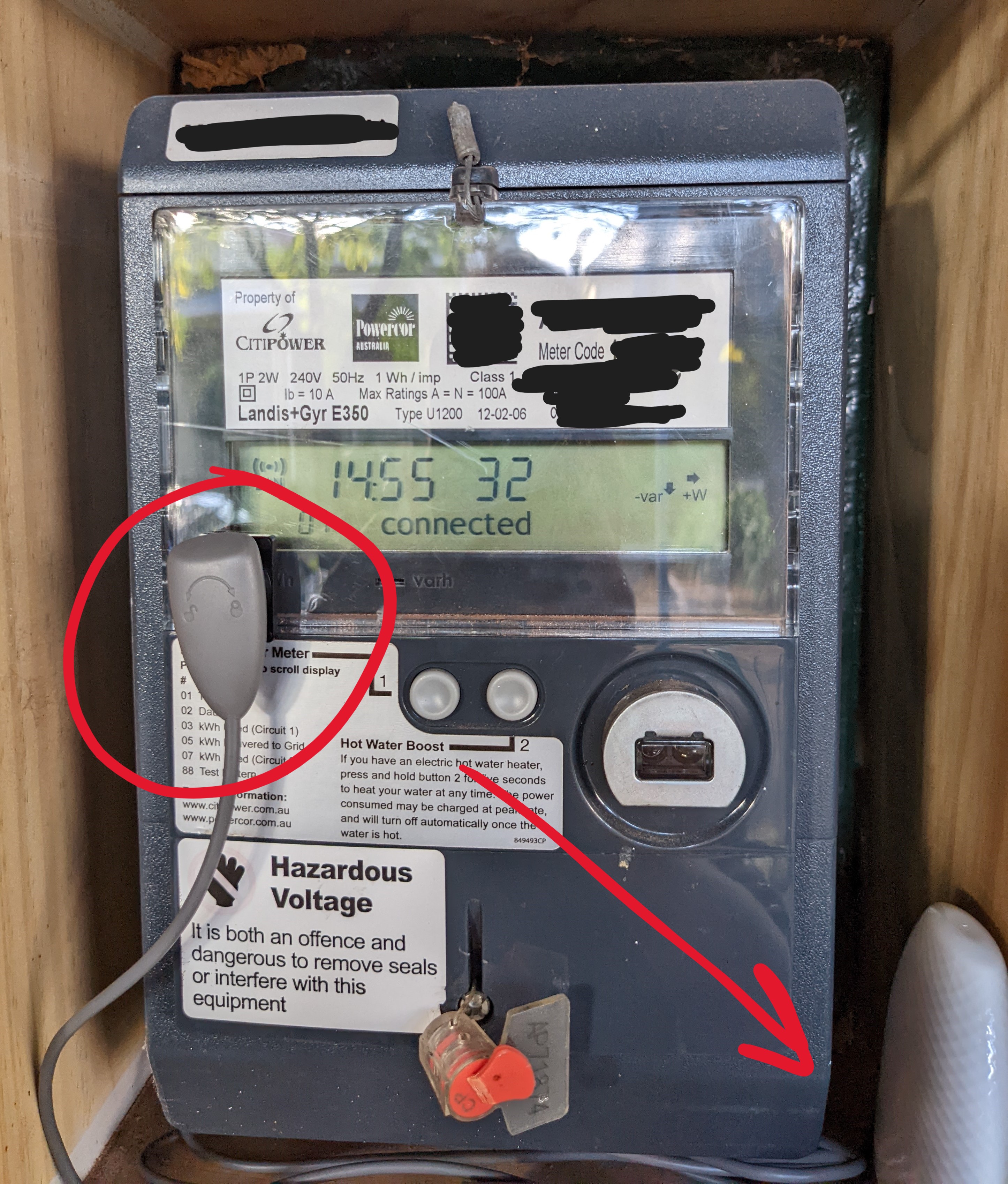
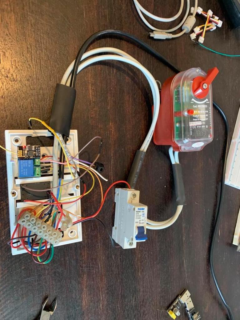
The physical integration is so incredibly simple: the meter has a red LED that blinks on a defined interval, and they just stick a sensor on top of it which counts the blinks. For our meter, it’s one blink per watt-hour (Wh) of energy. (It says “1 Wh / imp” on the front of the meter.)
Our smart meter with the Powerpal installed
The device itself is battery powered, as paradoxically the one place that you usually don’t have an easy wired power source is at your meter. Thanks to the magic of Bluetooth LE, it has an expected lifespan of 3-5 years.
The whole thing fits inside our existing meter housing (* once I took the drill to the inside of the door to route out just a little more depth for the sensor):
It’s a managed install, as they need to demonstrate that it’s working to claim the government rebate. I signed up on their website at 7am on a Tuesday, had the installer turn up at noon on Thursday, and it was all done in under 10 minutes.
With the first real-time insights (~10 second interval) into our usage, it was then incredibly easy to just walk around the house turning specific appliances on and off and seeing their specific draw. It wasn’t practical to do this type of isolation with the previous 30-minute reporting window.
This kept us entertained for a while, but we also had to learn to stop looking at it. It’s very real-time, so it’s easy to get jumpy about things which draw a high amount of power for a short time (OMG THE TOSTER IS ON!!!), or to optimise to a world where you have low energy usage but you’re also just cold.
The insights are good, but the Bluetooth LE connectivity brings several restrictions: you must have your phone in range of the meter, you can only have one phone connected at a time, and it’s not integrated with the rest of our home automation ecosystem so there’s no easy way to correlate historical usage with what else has been happening around the house.
It’s a good-enough solution, and great for mass-market access, but we wanted something more integrated.
Home Assistant Energy
We use the fabulous Home Assistant platform to run all our automation. It’s open source, exceedingly capable, and very actively maintained (top ten project on GitHub). It can be deployed on a Raspberry Pi, or there’s Home Assistant Yellow – first-party hardware that wraps a Raspberry Pi Compute Module with extra smart home radios (Zigbee, OpenThread).
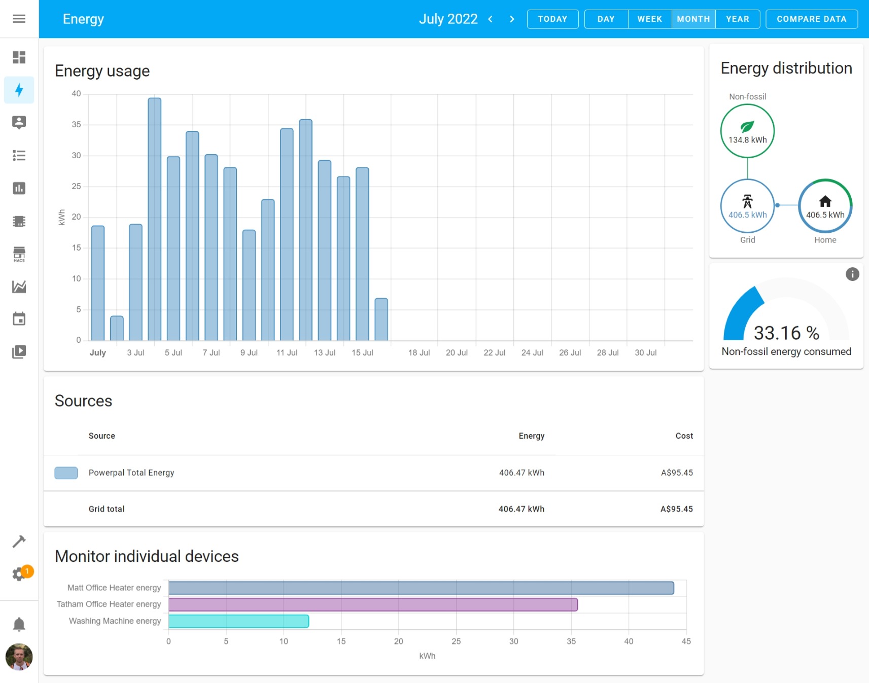
We’re still exceptionally early in our adoption of this capability, but we now at least have our grid-consumption and some specific load monitoring integrated:
Screenshot of our Home Assistant Energy Dashboard
In addition to all of the real-time sensors, data is also aggregated hourly, daily, weekly, and monthly. We can compare periods with prior periods. The dashboard here is just building on standard sensor entities within the Home Assistant ecosystem, so they can all be used to drive automations as well.
The “non-fossil energy” is defined as sources like solar, wind, hydro, and nuclear. Home Assistant sources this information from a service called CO2signal, for our specific part of the grid. Even though we’re paying for 100% renewable energy via Powershop’s GreenPower, we still consume from the same grid as everyone else, so the mix changes throughout the day, and it’s interesting / horrifying to capture that number over time.
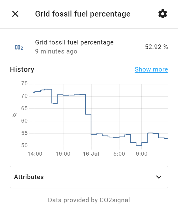
The CO2signal data is exposed as sensor.grid_fossil_fuel_percentage (%) and sensor.co2_intensity (gCO2eq/kWh), so they can be individually plotted, and used to drive alerts or automations however we see fit:
Home Assistant entity view for sensor.grid_fossil_fuel_percentage
But where does the grid consumption and individual load data come from?
Load Monitoring
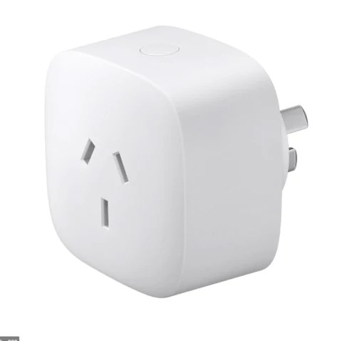
For specific high-power appliances, we’ve added Aeotec Smart Plugs to them. These are Zigbee-based smart plugs with built-in energy monitoring.
Aeotec Smart Plug
For panel heaters in our offices, we’re able to automate them turning on when we’re working from home and monitor the power (real-time) and energy (cumulative).
By having it all in the same platform as the rest of our home automation, we’re able to mash up this data with other sensors. This view is showing the power consumption of our heaters yesterday, along side temperature data from those same rooms, our front porch, and the nearest Bureau of Meteorology observations at Melbourne Olympic Park:
Screenshot of Home Assistant history view for specific entities
We can also use this data to detect what appliances are doing, like when the washing machine has finished. We have an automation that triggers when the machine starts using power, then waits until it has used no power for 5 minutes. After that, it sends a push notification to our phones. Here’s the YAML version of that automation, but the same could easily be configured in the UI if that’s more your jam:
This file contains hidden or bidirectional Unicode text that may be interpreted or compiled differently than what appears below. To review, open the file in an editor that reveals hidden Unicode characters.
Learn more about bidirectional Unicode characters
⚠️ Update Jan 2024: The code used in this section has atrophied, since ESPHome did a big push around Bluetooth capability in 2023 and changed some signatures. The example below won’t compile on ESPHome since build ~2022.12. I have not put any effort into fixing this, as my local firmware remained stable for quite a while after, and I have subsequently stopped using Powerpal. (We installed solar in Apr 2023 and re-did all of the energy integrations then.) The concepts in this section remain valid, so you can always give it a go and update the code yourself.
The other part of the puzzle was to get Powerpal data flowing through to Home Assistant.
I mentioned earlier in the post that the Powerpal device only exposes data over Bluetooth LE, to one device, which is great for a simple consumer setup but is quite restrictive for what we wanted to achieve.
There’s an article on their support site stating that they’re working on an API, and they specifically name Home Assistant as a target platform. To do this, they’re exploring a Bluetooth LE to Wi-Fi bridge as a separate device. (There’s no way that the device itself could directly connect to Wi-Fi otherwise the battery life would drop from 3-5 years to 3-5 hours.) There’s a beta signup form, which I filled in maybe six months ago, but I have no sense of how fast they’re progressing this, so I’m not holding my breath waiting.
There’s also a big red block of text that says you should absolutely not attempt to tamper with the existing Bluetooth LE connectivity, citing “potential data security risks”.
Let’s do that. Red text always sounds exciting.
Considering it’s all local communication, I don’t really see how Powerpal can stop me here, and it’s all extremely low risk work as there’s no active control of anything.
Time to make our own Powerpal-compatible (but totally not tampering) Wi-Fi bridge!
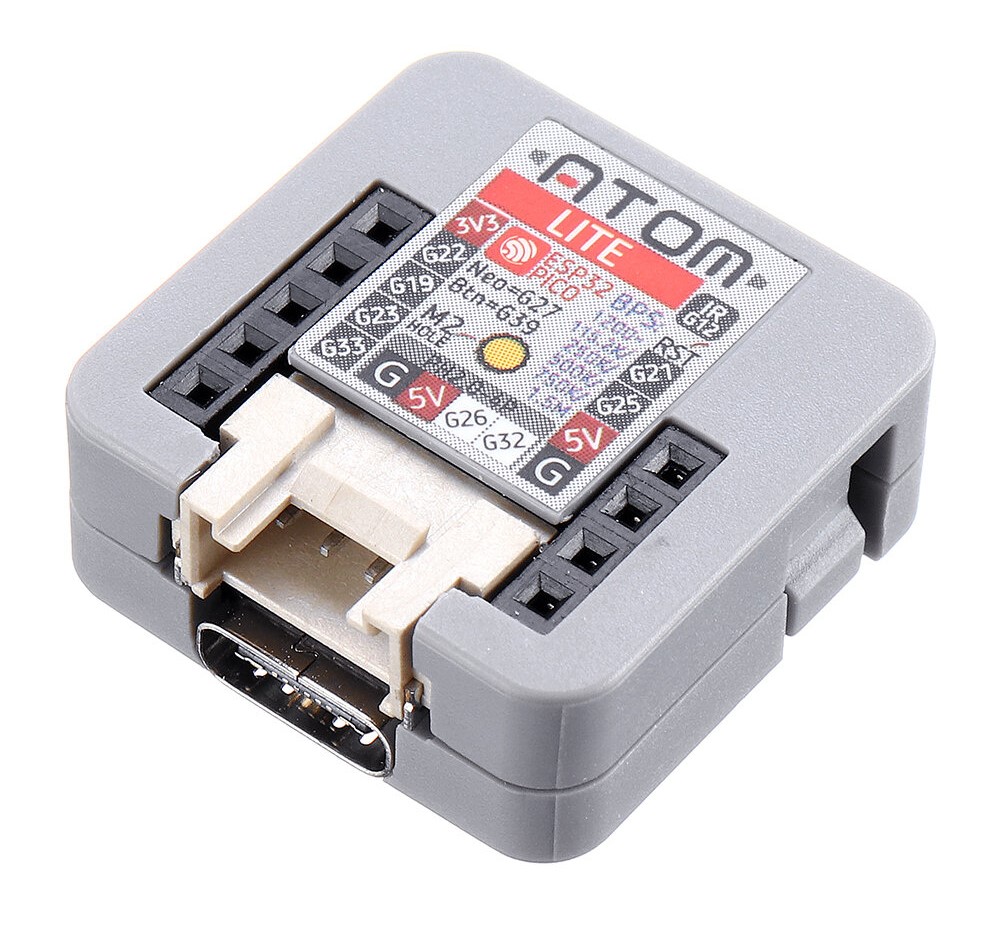
The device I’m using is an M5Stack Atom Lite. They’re US$7.50, tiny (24x24x10mm!), and USB-C powered. I’ve written about the versatility of them before. The chipset in them – an ESP32 – sports a 240MHz dual core processor, and a dual-stack Bluetooth + Wi-Fi radio, so it covers everything we need.
M5Stack Atom Lite
To make the firmware for it, I’m going to use ESPHome. This project is specifically focussed on making it really easy to generate firmware for ESP8266 or ESP32-based devices to talk to Home Assistant. You basically just give it a config file, and it does the rest. Getting going is as easy as installing the ESPHome Add-on in Home Assistant.
In my local instance of ESPHome, I created a new device called powerpal_gateway. Then, in just 45 lines of config, we can describe everything we need to generate the gateway’s firmware. If you’re a beginner to this type of thing, you can just copy-paste this whole block into ESPHome.
This file contains hidden or bidirectional Unicode text that may be interpreted or compiled differently than what appears below. To review, open the file in an editor that reveals hidden Unicode characters.
Learn more about bidirectional Unicode characters
This file contains hidden or bidirectional Unicode text that may be interpreted or compiled differently than what appears below. To review, open the file in an editor that reveals hidden Unicode characters.
Learn more about bidirectional Unicode characters
We need to provide the Powerpal’s MAC address (physically printed on it), and the pairing code (supplied on a card when you get it). That’s all that’s required to authenticate. As a matter of practice, I split these secrets out into separate variables. There’s a “Secrets” button top-right in the ESPHome web interface to manage them.
For the first time loading firmware on to the M5Stack, we need to plug it into a laptop. Then, in ESPHome, we can choose the device > Install > Plug into this computer. ESPHome will take care of pulling in all of the dependencies, compiling them into a firmware binary, and then helping us flash them onto the device right from the browser (using Web Serial).
We also need to make sure our phone is disconnected from the Powerpal, otherwise our new gateway won’t be able to connect, so it’s a good idea at this step to either turn Bluetooth off on the phone, or just go ahead and uninstall the Powerpal app entirely.
After that first flash, the device can be disconnected from the laptop, and just plugged into any regular USB power brick. Future firmware updates can be done wirelessly / over-the-air. At this point, I moved the new gateway to its permanent home in an out-of-sight location near the front hall, so it had good proximity to the meter box.
Once the new gateway has a minute or so to power up and negotiate with everything, we start seeing data feeding into Home Assistant. Success!
Screenshot of Home Assistant device page for the gateway
Now that the sensors are available, we can add them to Home Assistant’s energy dashboard via Home Assistant > Settings > Dashboards > Energy > Electricity Grid > Add Consumption. You’ll need to wait until the hour turns over (e.g., 10:00, 11:00, etc.) before the first batch of statistics gets calculated and everything really shows up.
The “Total Energy” measure resets to zero each time the M5Stack boots up. This is mostly fine, as it should be a very rare event anyway, and Home Assistant’s statistics platform knows how to handle it, as the sensor is defined as a ‘monotonically increasing total’. If you need to unplug the device to move it or something, then the lowest data loss path is to do it across the end of the hour (e.g., unplug it at 10:58 and have it powered back up by 11:02).
We also added the real-time power usage, today’s energy, and yesterday’s energy, to the main dashboard. (Create a Utility Meter helper to get the daily sensors. It’s ~10 clicks.) That replaces the Powerpal app for us, and brings energy into our single pane of glass experience:
Real screenshot from our Home Assistant mobile app experience
Summary
Just these few data points were a huge step for us to understand and optimise our electricity usage.
Considering the Powerpal was free, the only cost to integrate the grid energy data was the US$7.50 M5Stack. The Aeotec smart plugs were a bit more expensive (~AU$50 each), and we already had the Home Assistant instance running.
We now have environmental (temperature, humidity) and energy data into the same platform, so we can do smart automations and analysis in the one place.
We’re building longitudinal data. (Home Assistant feeds out to InfluxDB if you want as well.)
We’re able to monitor this from multiple devices, anywhere, anytime, thanks to Home Assistant acting as the broker, and Home Assistant Cloud for remote access. This is a marked improvement on the one-device-within-10m starting position of the Powerpal.
We’ve still got a lot further that we want to go. We’re installing solar next. I’m looking at the Schneider PowerTag range for circuit-level monitoring of the air conditioning. I’d like to bring in an intra-day view of our gas consumption.
And, like all smart home projects, it has just been nerdy fun to get this far. 🤓 None of this had to be done, but it could be done, so we did.
Jan 2024 Addendum
We installed solar in April 2023, powered by Enphase micro-inverters. This system provides data around solar production, house consumption, and grid import/export, based on a set of CT clamps connected to the Enphase Envoy controller. This data is then exposed over a nice, local-network API, on a 10sec refresh rate. We now use this data to power the energy dashboards in Home Assistant instead and have decommissioned our dependency on Powerpal. The best Wi-Fi setup for infrastructure is an Ethernet cable; I ran one to where the Enphase Envoy controller was being installed and never gave the installers any Wi-Fi details. Reliable, wired data, over a documented local API: win.
We also bought a farm last year and were back at the start line for energy monitoring on the property. A fresh HA instance, and a blank canvas for integration! We’ve deployed a Shelly Pro 3EM into the main board. This is a DIN-mount energy monitor, with three CT clamps, and a local-network API, on a 1sec refresh rate. The CT clamps are then clipped around existing AC circuits. The property only has single-phase, but we use the three CT clamps to measure: a) grid import/export, b) solar generation, and c) house usage (a separate circuit, which is a subset of the broader property). Again, the best Wi-Fi setup for infrastructure is an Ethernet cable, which the Shelly Pro 3EM supports. Reliable, wired data, over a documented local API: win. The only downsides to this device are cost (AU$200), and the need for a qualified sparky to install it.
Home Assistant has in-box / native support for both of these devices. As soon as they show up on your network, HA will auto-detect them and offer to bring them in.
Mum’s quite sensitive to air quality: she struggles with smoke during bushfire season, and pollen or dust at other times of the year. Declining air quality isn’t always as visually obvious as smoke, so an early warning for changing conditions helps. We want to know to close the house up before the indoor air quality gets compromised. When the outdoor air quality improves, we want to know that it’s the right time to open the house up.
My parents live in a rural setting, so for this type of thing we really need to source our own local data, rather than just looking at a region-wide feed.
🎁 Today’s electronics project: an air quality monitor.
One for inside, and one for outside. USB-powered. Wi-Fi connected.
The Sensor
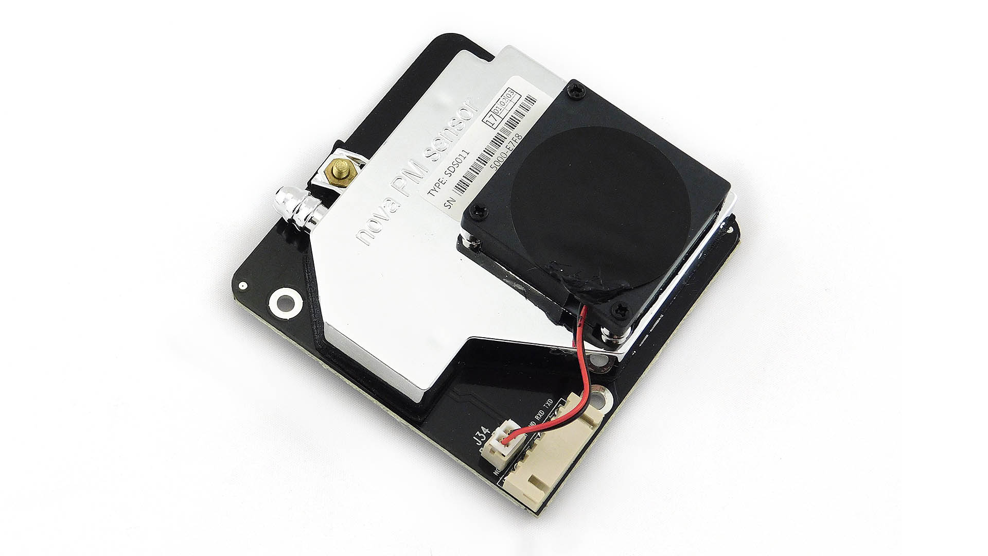
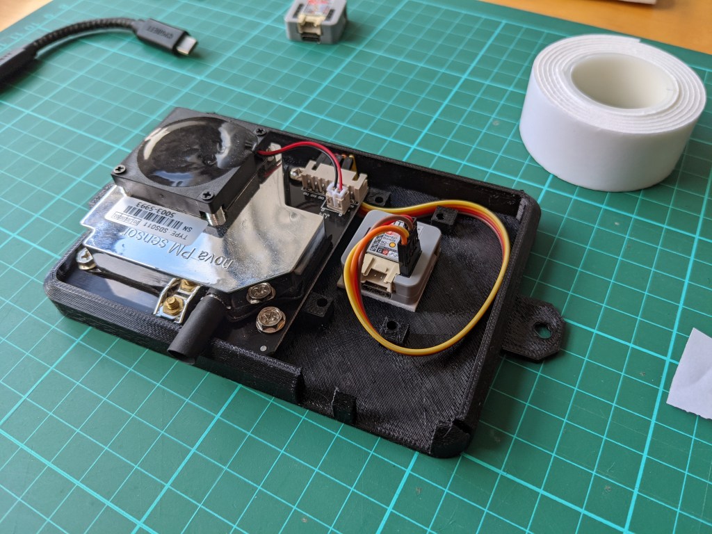
We’re interested in measuring particulate matter, like ash and pollen suspended in the air, as opposed to gas mix. The go-to sensor for this is a Nova PM SDS011. The sensor comes mounted on its own PCB, around 5cm square, with an integrated fan.
Nova PM SDS011 sensor
Every few minutes, the sensor fires up the fan on top, and sucks a sample of air from the intake tube you can see top-left, into the metallic box area.
Inside this box, it shoots a laser through the air, and then measures the scattering of the laser.
From this, it can determine the concentration of different sizes of suspended particles in the air.
We had a prototype running for a good year or more, and it was working well, but we were overdue with boxing it up nicely.
The Case
First up, we needed a case. Gone are the days of the generic project box from Jaycar, but this is my first foray into 3D printing.
https://www.thingiverse.com/ > Search > SDS011 found lots of existing designs, for this exact scenario. Wunderbar.
I ended up picking this design, by @sumpfing. There’s a “tip the designer” option in Thingiverse, but unfortunately she doesn’t have this enabled, so all I can do is say “Dankeschön!” a few times.
Case design from Thingiverse
It includes space for a DHT22 temperature/humidity sensor as well, in that square breakout back-right. It supports mounting for outdoor, and will happily sit on a shelf for indoor.
From Thingiverse, I was able to just download the design as a collection of STL files.
Rather handily, Windows 10 has native preview support for STL files. 💪 You can just double click the files and get an interactive preview without any additional software.
Windows 10’s built-in Print 3D application
For extra bonus points, open the file in “Paint 3D” (also built-in to Windows 10), then hit Mixed Reality mode.
You can drop the model straight on to the workbench next to the real sensor. This was a really handy way to get a sense of scale, and how the pieces would ultimately go together.
Windows 10’s built-in Mixed Reality preview mode showing real sensor and preview of case side-by-side
At this point, I’m sold on the design, but I don’t own a 3D printer. I have no interest in owning, calibrating, or maintaining a printer. Zilch.
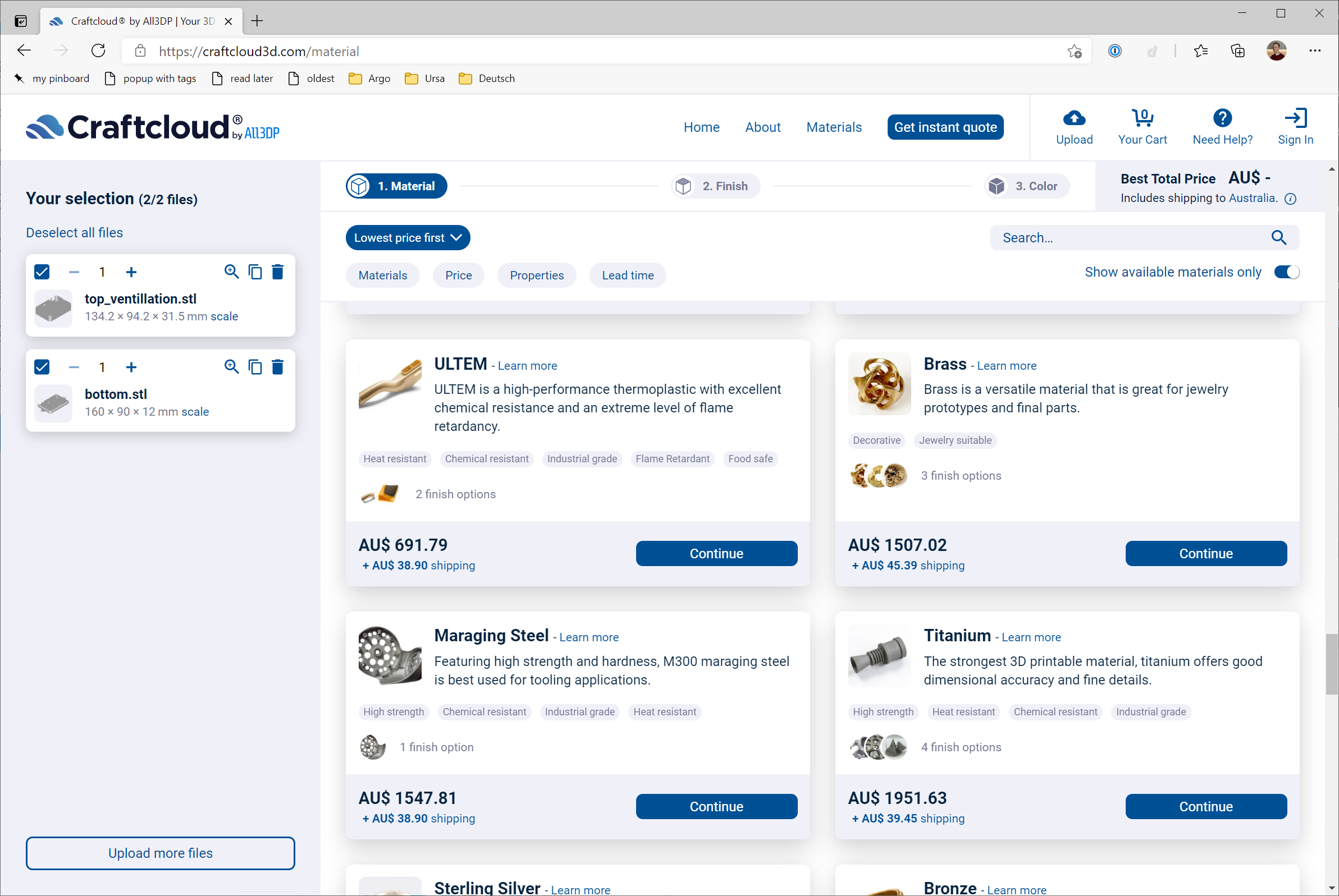
To the internet! Some quick Googling led me to Craftcloud, which provides a great marketplace experience.
You start off by uploading the STL files, and they generate a whole stack of quotes based on different materials, finishes, and operators from around the world.
So … will this case be brass, maraging steel, or titanium? 🤔
Craftcloud Quotes
I took the wild choice, and opted for cheaper black plastic. Specifically, something called PETG. I have no idea if that was the best choice or not, but it sounded versatile enough. I also chose a local, Melbourne-based printer, offering a 6-8 day turnaround.
No doubt I can optimise this purchase path in future, but Craftcloud earnt their money here for ease of access for a first-timer. I spent $46 on the case, and then nearly half again to ship it three suburbs.
Craftcloud Checkout
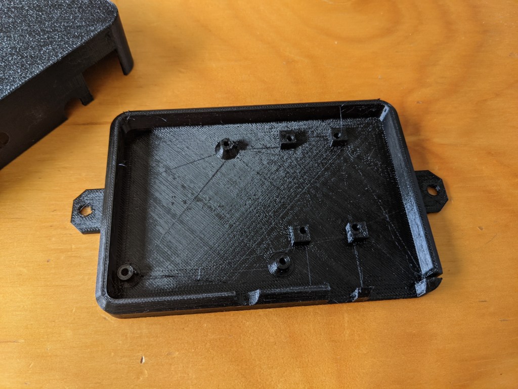
A few days later, we have a case! 🥳📬
The top section snaps on snugly.
The particulate sensor fits perfectly.
It’s black plastic.
Satisfied Tatham.
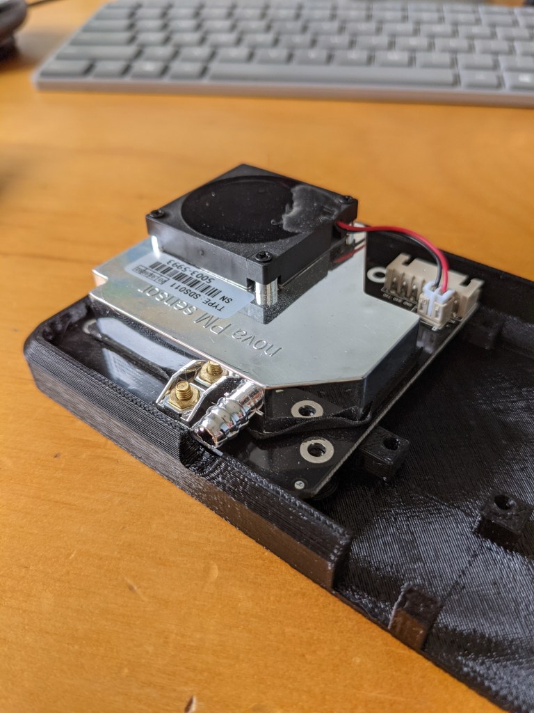
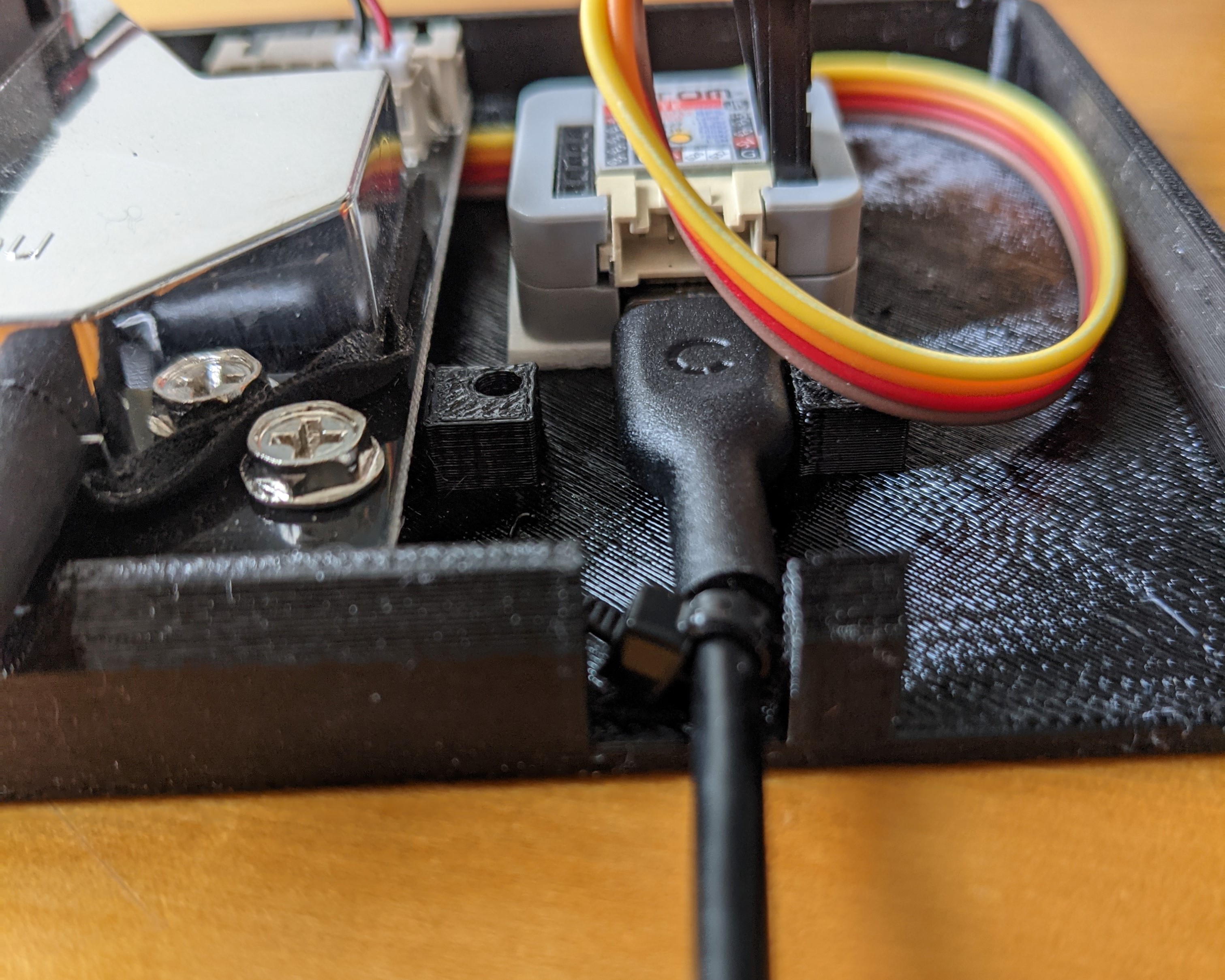
The sensor pops right into place, and anchors in easily with three screws. These are just random left over PC tower screws, probably from old hard drive mounts or something. I have a whole ziplock bag of them and they’re endlessly useful.
Sensor screwed into case
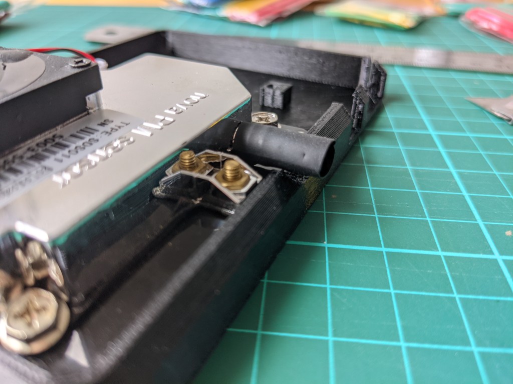
The intake tube is a bit short when the top of the case is popped on. I’m worried that it’ll suck air from inside the case, which would have it contaminated by its own exhaust.
This is easily fixed with a short section of heatshrink to the rescue, just slipped on (not actually heated).
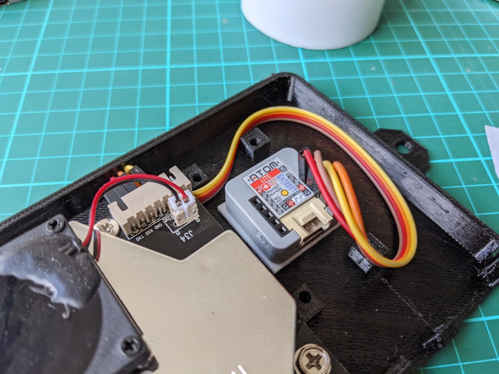
For the compute + Wi-Fi module, it’s a trusty M5Stack Atom Lite, for ~AU$10.
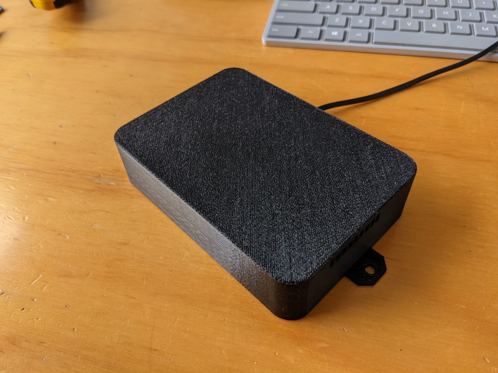
The top of the case just pops on with a little pressure.
This can now subtly sit on a shelf, or be mounted under an eave outside.
The Software
Time for some software.
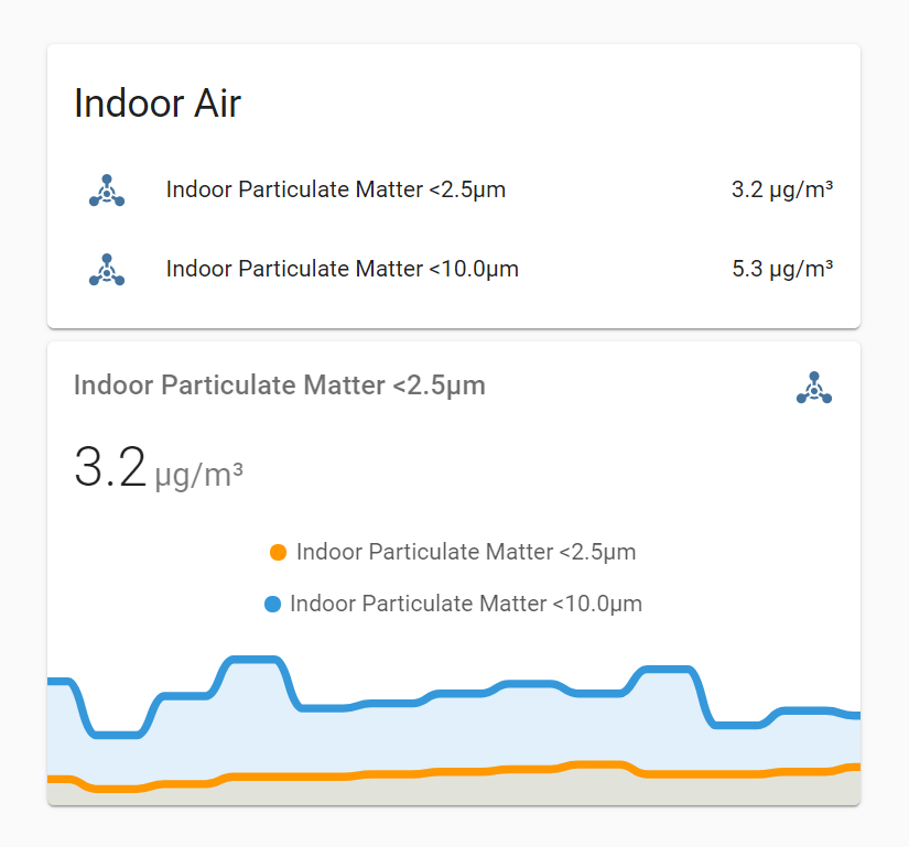
Thanks to ESPHome, it’s only 58 lines to get it connected to my Wi-Fi and have each particulate concentration (<2.5µm, <10.0µm) reported every 5 mins. Bonkers, but true.
It takes me ~15mins to create and deploy this firmware.
This file contains hidden or bidirectional Unicode text that may be interpreted or compiled differently than what appears below. To review, open the file in an editor that reveals hidden Unicode characters.
Learn more about bidirectional Unicode characters
We now have particulate matter concentration showing in @HomeAssistant. 🥳🎉
Values and trend chart in Home Assistant
From here we need to:
Add the DHT22 temperature and humidity sensor when it arrives, to complete the build.
Build a second box for outside, so we can decide when to seal-up vs. air-out the house, based on indoor/outdoor differences.
Trigger a push notification when particulate-matter is increasing, to say ‘close up the windows now’.
PS. This project was originally shared on Twitter. Jump over there for the discussion.
😷 Mum's quite sensitive to air quality, and struggles with smoke during bushfire season. It's not always as obvious as smoke though, so an early warning for changing conditions helps. This is hyper-local data.
Emad Alashi – a long-time coworker of mine – recently blogged about a soil moisture sensor that he’s built using exactly this combination of M5Stack Atom + ESPHome. He’s working on battery power, and thus needs to put the device into deep sleep most of the time to conserve energy.
The challenge: Combining deep sleep behaviour with over-the-air updates. It’s incredibly hard to push an over-the-air firmware update to the device when it’s only awake for a few seconds at a time!
The solution: Publish a flag that says “stay awake”. When the device next wakes up, it’ll read this flag, and skip a further sleep cycle. It’s essentially an advertised maintenance mode.
Emad hit this challenge in his project and implemented the solution that’s documented with the ESPHome Deep Sleep Component.
That solution relies on an MQTT broker holding the message, and the device checking for this pending message on boot:
I wanted to document an alternate approach, that avoids the need to introduce an MQTT connection, and sticks with a purely Home Assistant-native approach instead.
One of the things I really like about ESPHome is how natively it is integrated with Home Assistant, and the entity model that’s already there. Let’s avoid adding another protocol and set of messaging concepts in the mix.
Introducing a Global Flag
First up, we need a way of storing the “please stay awake” flag.
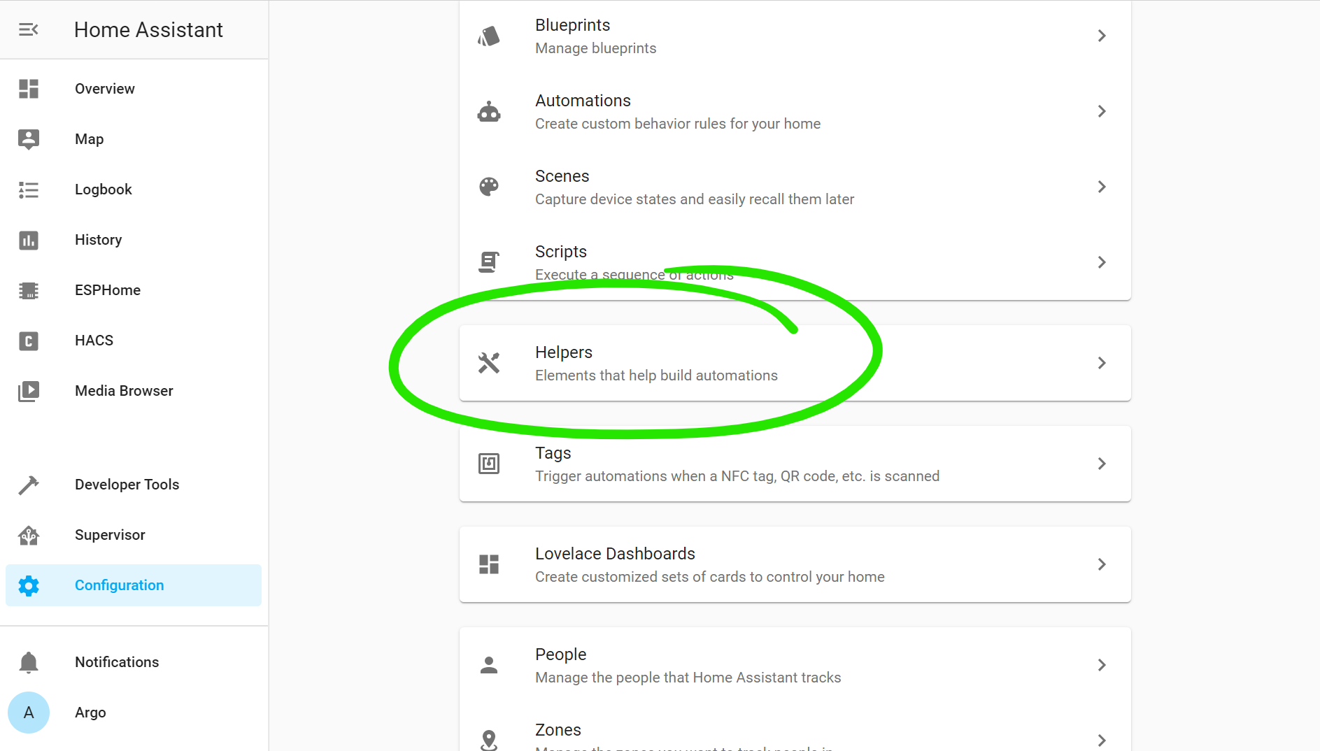
Home Assistant has the concept of “helpers”, which are just easy places to store an extra little bit of state like this.
They’re available in the web interface under Configuration > Helpers.
Screenshot of Home Assistant Configuration screen
I’ve gone ahead and created one for our flag. This will be a single global flag, that all of my sleep-aware devices can watch and respond to.
Type
Toggle / Boolean
Name
Prevent Deep Sleep
Icon
mdi:sleep-off
Entity ID
input_boolean.prevent_deep_sleep
Helper configuration
Screenshot of helper configuration screen
If you’re more of a fan of managing Home Assistant via configuration.yaml, you can declare the helper there too:
input_boolean:
  prevent_deep_sleep:
    name: Prevent Deep Sleep
    icon: mdi:sleep-off
When our device boots up, and connects to the Home Assistant API, it’ll read the helper value in to the local state. If Home Assistant isn’t connected, or is offline, it’ll default to false.
⚠ Important note: The connection is actually triggered from Home Assistant to the ESP-device, and it’s only initiated if the device is setup under Home Assistant > Integrations. Just because you can see the device in the ESPHome web interface doesn’t mean it’s actually setup as an integration. If your firmware seems to be ignoring the helper value, it’s probably not actually connected.
With the value available, we can now combine that with the deep_sleep component to setup the right balance of power saving logic.
Here’s the complete, working ESPHome config for an M5Stack Atom Lite:
This file contains hidden or bidirectional Unicode text that may be interpreted or compiled differently than what appears below. To review, open the file in an editor that reveals hidden Unicode characters.
Learn more about bidirectional Unicode characters
Now I have a simple, global toggle when I want to put devices into development / maintenance mode.
The process becomes:
I want to do some device maintenance
I turn the “Prevent Deep Sleep” toggle on in Home Assistant
Over time, all of the different battery-based devices come out of their regular sleep cycles, and then stay on
I do the maintenance I want
I turn the “Prevent Deep Sleep” toggle back to off
All the devices resume their normal, power-saving sleep cycle
No extra brokers or message constructs had to be deployed. 🤘
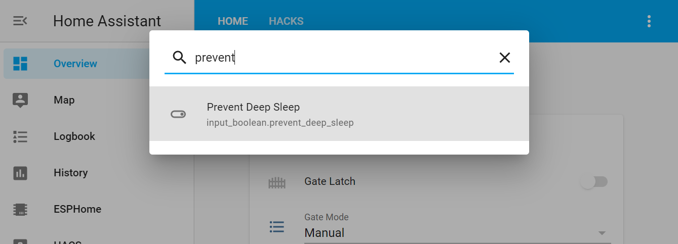
Tip: Quick Bar
I don’t really want to add this toggle to the regular UI surface in Home Assistant, but I also don’t want to go digging for it in the dev tools every time I want to turn it on or off.
Home Assistant includes a ‘quick bar‘, modelled off the command palette in VS Code.
Just press e (for ‘entity’) as a hotkey anywhere in the frontend, then type the name of the toggle:
Our goal is to be able to quickly and cheaply integrate new sensors and controls. We want to be able to buy a flow meter / particulate matter sensor / pressure transducer / other crazy thing off AliExpress, and get it integrated into our control plane without it becoming a massive project.
Too many electronics and automation projects just die on the desk. We want the flexibility of our own electronics, but we want to be off the breadboard and into production as fast as we can.
As a software developer, the place I often getting tripped up is, amusingly, at the coding stage. Some fairly simple electronics suddenly need a lot of code to actually integrate well. Writing it yourself is a blackhole that’s easy to fall into.
Last year, I fell in love with ESPHome: the perfect piece of glue between ESP-based devices and Home Assistant.
This file contains hidden or bidirectional Unicode text that may be interpreted or compiled differently than what appears below. To review, open the file in an editor that reveals hidden Unicode characters.
Learn more about bidirectional Unicode characters
I live in an inner-city apartment. There’s a concrete slab, brick walls, and no ceiling cavity access. Oh, and we rent, so drilling into things is frowned upon. The home automation potential in a scenario like this consists of some coloured lights, and watering about four plants on a timer. It’s not exactly an inspiring IoT site. There’s also not much wrong with the humble light switch that works instantly, every time.
In complete contrast to this, my parents live on 100 acres / 40 hectares of land, a few hours out of the city. It’s quintessential rural Australia. They’re mostly off the grid: there’s a skerrick of Telstra 4G signal, and some power, except when there isn’t, which is surprisingly often. This is an absolute IoT playground, and we’ve given that a fair crack over the seven years as they’ve established themselves there.
Opportunity
On a property like this, water is critical. There are the basic living requirements, the opportunity of gardens, and the very real risk of bushfires. All up, we have ~300,000 litres of water tanks on the property, and then a small dam and two creeks. We use sensors to track tank volumes. We measure flow rates at key plumbing points (for both instantaneous oversight and tracking cumulative usage). We use power meters to detect when pressure pumps are running.
Energy management is also important. Whilst there is the option of grid connectivity, we try to run as off-grid as possible, or at least export-only. This requires some smarts around load management. For example, instead of just having a hot water system that aggressively chases a specific temperature, we want the hot water systems to head for a temperature range, but only use excess solar production to do it. If there’s a bit less sun for the day, it’s ok if the water it a few degrees cooler: don’t burn down the batteries or import power just to hit a specific temperature.
And then there’s a safety aspect. The property is on the top of an escarpment where storms can roll in fast from a few different directions. By running things like lightning sensors on the property, we can trigger our own localised alerts for approaching storms.
Challenges
The challenge is to convert all these possibilities into something real, that works, and doesn’t cost an absolute mint. Over the years, we found this incredibly hard to solve for. You’ll find a solution for measuring tank volume, but it comes with its own LoRA gateway, a cloud dependency, and a new app. You’ll find a cheap Z-Wave temperature sensor, but it’s only really good for a room, and doesn’t have a probe that you can put into the measurement point in a hot water system. You’ll find a flow meter, but it’s only an industrial solution that wants to talk RS485 serial. Who even does that anymore⁈ You’ll find a garage door opener that works for the extra-high roller doors on the shed, but it has its own 433MHz RF remote.
It’s easy to end up with a horrible mishmash of radio technologies, software platforms, and APIs, not to mention some scary pricing as you drift from the traditional world of home automation into the more dated world of industrial automation.
Goal
We want to be able to dream up crazy new ideas, pick and choose the right sensors, and then integrate them with relative ease and consistency. That means a balance between the ability to build new things ourselves, but not having to go and custom fabricate a circuit board and write new firmware just to add a new sensor.
Considerations
Sense
Most sensors give out some kind of analogue signal (like a pressure sensor where the output voltage varies from 0V to 5V depending on applied pressure), a pulse (like a flow meter that pulses once for every 500mL of water that flows through it), or a digital signal (like a temperate and humidity sensor with a 1-Wire output).
To handle all of these scenarios, we’ll need some GPIO pins (the most basic of digital connections), and something with an analogue-to-digital-converter onboard (so that we can measure that variable pressure scenario).
Affect
Most of the outputs that we’re dealing with are straight up binary: turn a pump on, open a valve, flash a light. This means that they can be again driven by some GPIO pins, paired with an appropriately sized relay.
For more complex outputs, like sound, we can defer back to more consumer-grade hardware, like just broadcasting an announcement on the Google Home speaker in the kitchen.
Plug and Play
As much as we’re building things ourselves, we don’t need to put too many barriers in front of ourselves. We’re after a module that we can connect sensors to easily, without too much soldering, and certainly not having to build up our own circuit boards / Veroboard. We want to be out of the lab and into the environment as fast as possible.
Secure
There’s a persistent joke about how the ‘S’ in IoT stands for security.
Security was absolutely a consideration for us though: both on-property, and when it comes to remote access. When you’re switching things like power, or controlling a precious resource like water, you want to be confident that you’re the only person in control.
Our preference has been to keep connectivity and control local to the property, via authenticated connections, and then apply a separate remote access approach further up the stack. This means the hardware needs to have enough power and smarts to handle secured local connections, and not be dependent on its own path to the internet.
Compute
Some sensors require both precise timing and persistence to count things like pulses and turn them into natural measures. For example, a flow meter might give you a signal pulse for very 500mL of water that flows through it. If you miss a pulse and stop counting for a bit, you’re missing water. Our preference has been to count pulses on the hardware attached to the sensor, and then report back the natural values (L/min, L/day) whenever the network and central compute is available. We want to keep sensor-specific concepts, like pulses, at the sensor, and just send meaningful information over the network.
As much as we want things to be connected, they can still be somewhat smart in their own right. If a hardware module has both a temperature sensor and a relay to turn a heating element on and off, it’s perfectly capable of being a thermostat on its own, regardless of what’s happening to the wider network or any centralised compute. It will be smarter when the central controls are online, because it can be aware of other datapoints like the solar charge status, but it doesn’t have to be totally bound to the availability of those other systems to operate its basic function. Achieving this balance requires us to be able to run basic logic directly on the module.
The world is not static. If we want to run logic on these devices, and keep them secure, they need to be able to receive firmware updates over-the-air. We don’t want to be clambering around under sheds with laptops to reprogram a thermostat.
Connect
Network standards are still the multi-billion-dollar question in IoT.
Early on, we deployed a number of Z-Wave and Zigbee based devices. These are two different mesh protocols, at the mid-point of their VHS vs. Betamax battle for dominance. They’re common in consumer automation solutions like smart switches, and good for extremely low power environments, like where you want to be able to throw a temperature sensor in the corner of a room with a coin-cell battery in it and then forget about it for a year. The sensor ecosystem is very consumer focussed (you’ll find a million temperate sensors, but no tank pressure sensors). The communication protocol is constrained: by design, it’s a very low bandwidth data network, operating up to 40kbps for Z-Wave, or a whopping 250kbps for Zigbee. Range is limited to keep within the power limits, so typically as low as ~15-20m. There’s no common way of building on-device logic, and if you do manage to, then it’s incredibly hard to apply firmware updates over-the-air for either of them.
Our exploration continued into LoRA and NB-IoT, but we’ve opted away from both for this property. They’d each be very compelling options if we wanted to cover the larger property, such as if it was more of a working farm with distributed infrastructure than predominantly bushland and gardens with clustered buildings.
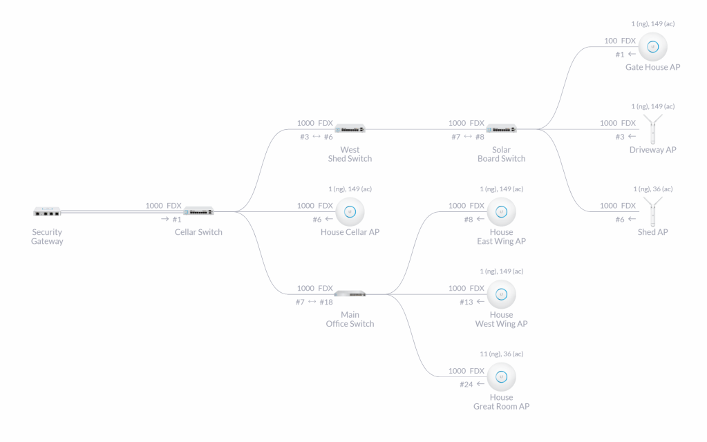
Ultimately, we settled on Wi-Fi as our preferred connectivity on the property. We’re already got great coverage throughout the house, cottage, shed, and key outdoor locations via a UniFi deployment. Whilst this is heavily centred on the built infrastructure, and not the full 100 acres of property, that’s where most of the sense-and-act needs to occur anyway. Investing in the Wi-Fi coverage provides other benefits, like Wi-Fi calling for mobiles where we’re otherwise on the fringe of 4G coverage. The UniFi infrastructure is readily extensible, as Lars has proven on his property with the deployment of Llama Cam, and even extending the coverage to places without power. Finally, it gives us a pretty amazing management plane that’s a lot nicer to work with than trying to diagnose a Z-Wave/Zigbee mesh.
UniFi infrastructure topology
Power
We’re happy to depend on a power source for most devices: they’re usually located near other loads that are already powered, or it’s easy enough to get power to them, such as dropping in a 12V cable out to a water tank at the same time as trenching the plumbing in. If we really want to run on battery, it’ll be ok to have a larger 12v battery and a small solar panel or something: we don’t need to try and run off a coin-cell battery for years on end.
Cost
The approach needs to be reasonably affordable if it’s going to grow over time: tens of dollars to add a new thing, not hundreds.
Whilst there’s no room to optimise on sensor cost, it does give something to calibrate against for the target cost of the compute module. We wanted to target ~$5 per module. It felt like the right cost, relative to the sensors themselves.
Hardware Options
So many options! Let’s run through them against those considerations:
Raspberry Pi
By this point, most software developers are jumping in with “Raspberry Pi! You can even buy hats for them!”. That’s certainly a response I started from. It feels safe: it has ports that you’re used to, you can plug in screens, it runs a whole operating system, and it has an IO header exposed for those plug-and-play scenarios.
Raspberry Pi 4
They’re also completely overpowered for what we need here. These things are small PC replacements: they’re full computers, not basic microcontrollers. Memory capacity starts in the gigabytes when we only need megabytes. They can run dual 4K display outputs when we only need to switch a couple of wires on and off. They need an SD card with a whole operating system on it just to boot. They suck up 3A of power, which is at the expensive end of USB power supplies. They’re also quite bulky compared to other options we’ll look at through this post.
A Pi, power supply, and SD card will quickly run to ~$50, which is 10x our cost target.
✅ Sense ✅ Affect
✅ Plug-and-Play ✅ Secure
🤯 Compute ✅ Connect
😐 Power ❌ Cost
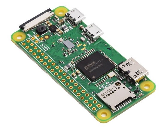
Raspberry Pi Zero W
This is as small as the Raspberry range goes, but it’s still a similar position as the main Raspberry Pi models: completely overpowered for this purpose, with a 1GHz processor, 512MB of RAM, and HDMI video output. Thankfully, it’s less power hungry, so we’re back into the range of any-USB-power-will-do. It’s also physically a lot smaller: look at the relative size of those micro USB ports.
Raspberry Pi Zero W
It still needs a micro-SD card in addition to the base board, which takes the bill up to ~$15, still 3x our cost target. From a plug-and-play perspective, you’ll have to first spend time soldering on your own header strip, or pay a bit extra for one pre-soldered.
✅ Sense ✅ Affect
✅ Plug-and-Play ✅ Secure
🤯 Compute ✅ Connect
✅ Power ❌ Cost
Arduino and Adafruit
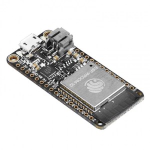
As we carve away ports and computer power that we don’t need, our next stop is the Arduino or Adafruit Feather range of boards.
Each of these ecosystems has a range of different connectivity options: boards that come with Wi-Fi, Bluetooth, LTE, NB-IoT, LoRA, or none of the above.
They have Wi-Fi on board, a USB port for power and programming, a stack of GPIO pins, and an analogue input. There’s no additional SD card required: there’s flash memory on the board itself. You can buy a version with pre-soldered headers, making that plug-and-play scenario easier.
The compute is right sized for basic sensors: an 80MHz processor with 4MB of flash memory attached.
The only thing on here that’s a little bit extraneous for our scenario is the Li-Po battery connection. (That’s the black connector at the top corner, next to the micro-USB.) The board can both run off a Li-Po battery, and recharge one, as there’s a charging circuit built into it as well. But, for our scenario where we said permanent power was ok, the charging circuit just adds more cost to the board.
Unfortunately, the boards are still up around $20, which is 4x our cost target. There’s also a lot of exposed electronics, so we’d need to factor a case into the price yet.
✅ Sense ✅ Affect
✅ Plug-and-Play ✅ Secure
✅ Compute ✅ Connect
✅ Power ❌ Cost
Discovering the ESP
What we’ve looked at so far in this post are different boards.
As I was researching around different boards, I kept running into phrases like “Arduino compatible”, and references to ATmega, ESP8266, or ESP32 chipsets.
It starts to get interesting when you split up the concept of a board, versus a chipset.
The chipset is the processor at the core of each of these boards: the smarts that makes it tick. There are a small number of very popular chipsets. There are then lots of different boards that package these chipsets up with other supporting systems and accessories to make them more accessible: USB serial drivers, voltage regulators, battery charge circuits, different breakout headers, and different physical form factors. It’s these extra systems that drive the cost up, and the brand recognition of the boards that drives the margin.
After some very nerdy reading 🤓, I got quite excited by the ESP range, specifically the ESP8266 and ESP32 chipsets. It turns out these are very popular with makers and manufacturers alike because they hit an interesting sweet spot of cost and capability. If you’ve got a Wi-Fi enabled smart plug in your house, there’s a decent chance that it has an ESP inside it.
These chips were never really designed as a general-purpose compute unit: the ESP8266 came first, and it was intended as a Wi-Fi modem, to be added on to some other device. It has enough compute to run a full TCP/IP stack, some leftover generic pins, and the ability to re-flash it with new firmware. There was originally only Chinese-language documentation, but the low price point and interesting feature set led the maker community off into investigating it further and translating the documentation. The manufacturer – Espressif Systems – saw the opportunity and jumped right in with the release of official SDKs and English-language documentation.
The ESP8266 was succeeded in 2016 by the ESP32 series, upgrading it to a 32-bit dual-core processor, more memory, Bluetooth support, and a stack more peripheral interfaces.
Both chipsets now have an excellent ecosystem of software around them. Of particular interest to me was the ESPHome project: it’s specifically targeted at generating firmware for ESP-based chipsets, to integrate with a wide range of sensors, and then link all of this back to Home Assistant, which is what we’re already using as the integration layer for everything on the property.
Now I could re-focus the search for boards to be based around these chipsets.
Two compelling solutions came to light:
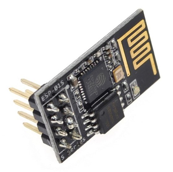
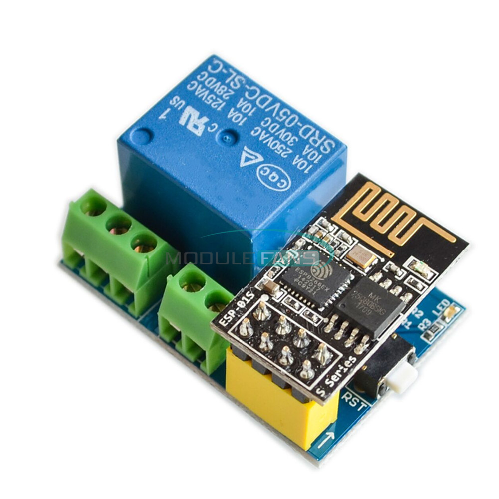
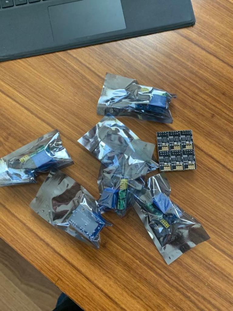
ESP-01S
These modules are positively tiny, at just 25mm × 15mm.
They’re an ESP8266 chipset, with just 8 pins exposed: power, serial comms (mainly useful for programming them), and two GPIO ports. That’s not very much exposed, but it’s just enough to get the job done when you only need to detect one thing and switch another.
ESP-01S module
At only ~$1.50 each, they’re at an incredibly compelling price point. That’s a custom programmable microcontroller, with Wi-Fi connectivity, for under $2. 😲
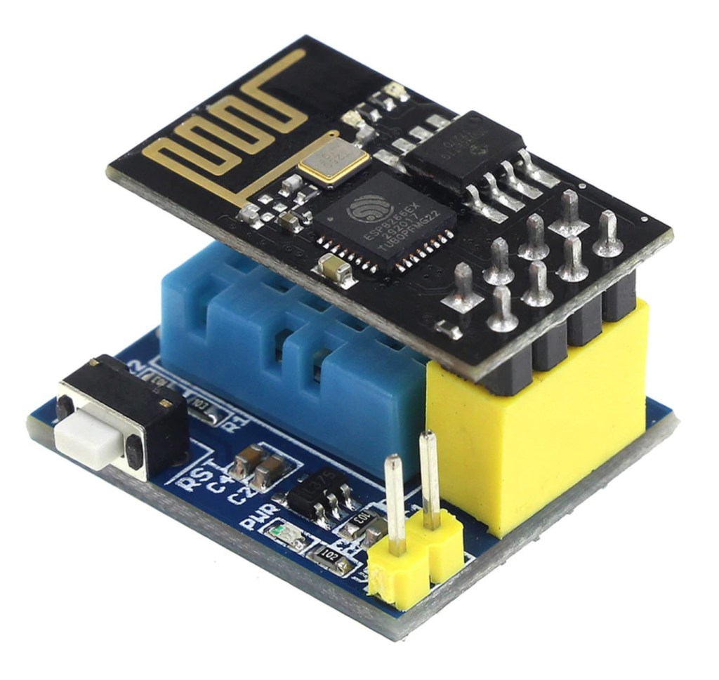
One minor annoyance is that they need to be powered by 3.3V, so you can’t just attach 5V from an old USB charger. There are however two very prevalent base boards: a relay board, and a temperature/humidity board. Each of these supports the ESP-01S just plugging into them, and can be powered by 5-12V. You can pickup the ESP+relay, or ESP+temperature combo for ~$3.
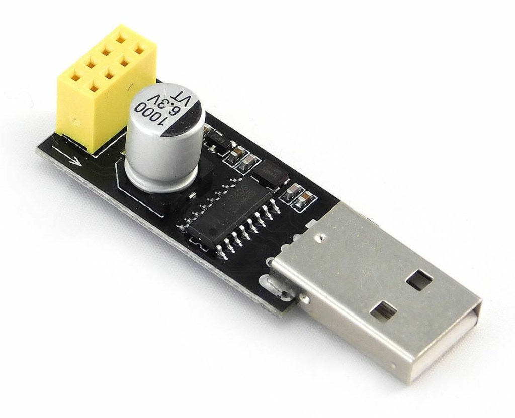
One frill they’re missing in their no-frills approach is any kind of USB serial driver. That just means you’ll need a separate programmer module for the first-time flash. Once you’ve flashed them once, you should be able to do future updates over-the-air.
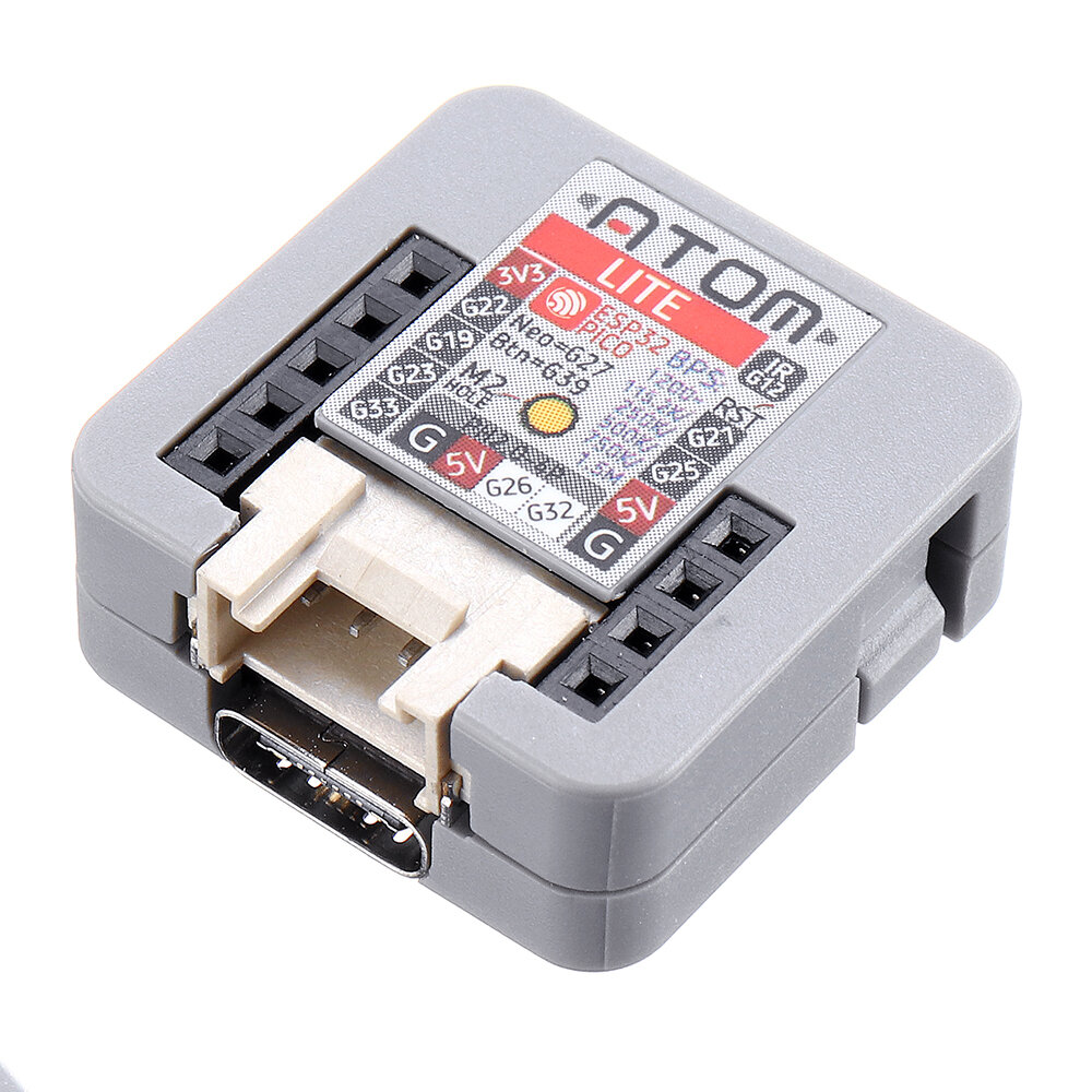
These modules are the absolute winner: they hit the perfect sweet spot of capability, ease-of-use, and cost. They’re more like a ready-to-go compute module than a dangling microprocessor in need of a breadboard.
They have an ESP32 processor at their core, nine exposed GPIO ports, a button, an LED, and an IR LED. They’re housed in a nice little package, so you don’t have exposed boards. They’re powered and programmed by USB-C. All for ~$5.
M5Stack Atom Lite
The pin configuration is documented right there on the case, making them incredibly easy to wire up quickly. The only piece that’s missing is to know which GPIOs support analog inputs, but you can cross-reference them back to the ESP32 pinout for all the per-pin specs.
Many sensors can be connected directly to the Atom Lite: plug in +3.3V or +5V, GND, and a signal wire to a GPIO pin. For quick construction, wires can be pushed directly into the exposed header sockets. For a more robust connection, you can add a Grove/PH2.0-4P connector to your sensor, and then plug it into the port at the bottom there, next to the USB-C.
The LED is actually a “Neopixel” which means that while it only uses up a single GPIO, it’s a digitally addressable tri-colour LED. We’ve used this to provide a multi-colour indicator right there on the device for quick diagnostics in-the-field.
✅ Sense ✅ Affect
🤩 Plug-and-Play ✅ Secure
✅ Compute ✅ Connect
✅ Power ✅ Cost
Pre-built solutions: Shelly1, Sonoff, and more
The prevalence of ESP chipsets continues to pre-built solutions as well.
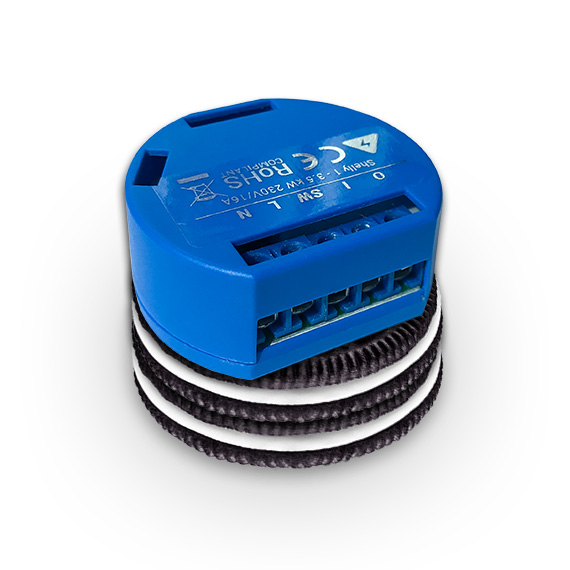
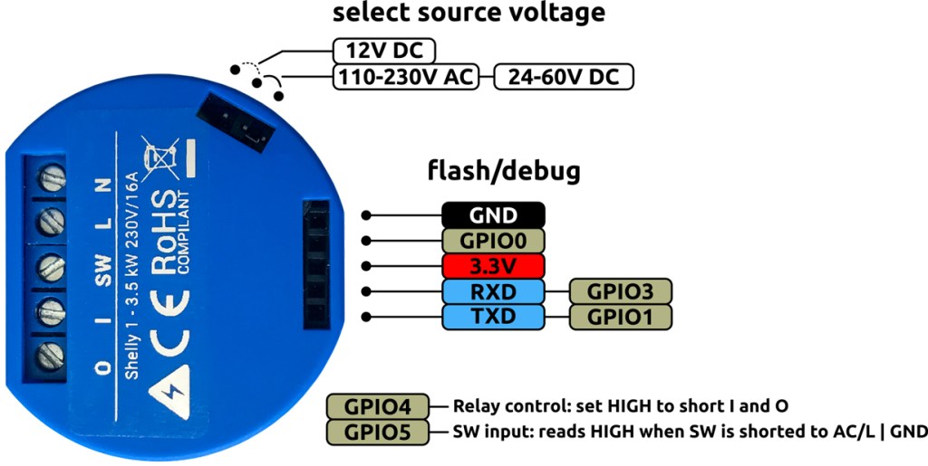
The Shelly1 is a 230v/16A-capable relay, designed to fit in to tiny spaces like behind an existing light switch panel. It can be wired in with an existing physical switch, so you still have the instant experience of a normal light switch, but now it can be Wi-Fi monitored and controlled as well. Here it is with an Internationally Standard Sized Oreo for scale:
They’re Australian certified, but you’ll still need a sparky to actually install them for you if they’re hooked up to your 240v circuits. For lower voltage circuits – like switching irrigation – you can wire them up yourself with a screwdriver and zero soldering.
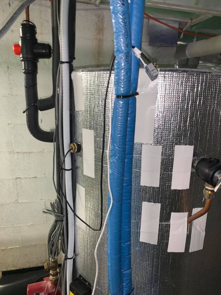
Here, an M5Stack Atom Lite ($6) is combined with a DS18B20 temperature probe (~$2, including 2m cable), a single resistor jammed across two pins, a leftover USB charge cable, and a little bit of electrical tape to hold it all together. For sub-$10, and no soldering, we have a Wi-Fi connected temperature sensor dipped into the hot water system, connected back to Home Assistant.
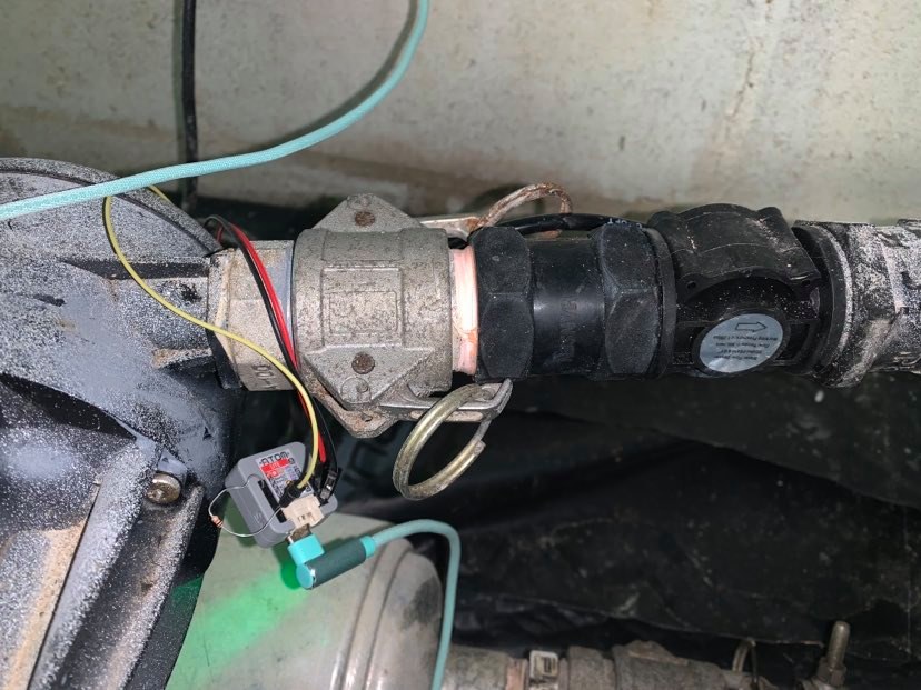
A similar setup connects to a flow meter in-line with a pressure pump. The flow meter draws power (3.3V and ground) straight off the M5Stack. For each litre of water that passes through, it’ll pulse 11 times. A resistor is jammed across the pulse return and ground to remove float noise. The flow sensor can cost anywhere from $5 to $500 depending on what pressure you want to be able to handle, for what type of fluid, and to what accuracy. Ours cost ~$20, so the whole setup was <$30. It’s not the nicest fanciest of engineering, but it was zero soldering, and it hasn’t missed a pulse yet.
ESP-01S modules with corresponding relays litter Dad’s desk by the bundle. Right now, he’s building out a relay control, with active feedback, for an otherwise dumb valve. It’s a complex valve that takes 15 seconds to move fully from one state to another, due to the pressure it can handle. This is a perfect scenario for local logic: we can use an ESP-01S to drive the valve for the right amount of time, and then validate the expected state against the feedback wire. A dumb valve becomes a smart valve for <$10.
It’s Monday, and you’ve picked something to work on: we’re finally going to get that new policy launched internally. We just need to write up the post and get it out to the team. It’ll be done and live by tomorrow. Maybe Wednesday at the latest.
Hold on; we missed a scenario. Alex can help fix that. Got five Alex?
Great chat! That really helped, and thanks for pointing out those other stakeholders we missed. We’ll check in with them quickly.
It’s Friday morning. They’ve found a gap. It’s annoying, but it’s good that we found it, and we can fix it quickly this morning.
Hey folks! I think we’re ready to go, yeah? We really need to get this out this week!
It’s now 2pm Friday.
Stop. Don’t publish.
Work can be like a gas: it expands to fill the container. The easiest scheduling container is a working week: it starts fresh on a Monday with a new burst of optimism, then everyone’s mutual optimism collides into a ball of messy work, and finally culminates with everybody wanting to feel successful before closing off for the week. It’s nice to tick off the ‘simple’ things you set out to achieve at the start of the week, especially if they evolved into something not-so-simple.
There are very few things that make sense to publish after noon on a Friday.
Your end-of-week rush collides with everyone else’s. When most people are also in output/closing mode, it’s hard to effectively inject new input.
Your comms won’t be perfectly contained or reaction-less. Hopefully they’ll be quite the opposite! People will have questions or feedback. They’ll have scenarios you didn’t contemplate. All of these are ok, if you’re able to respond effectively. You could leave the responses until Monday, but that’s a bit of a dump-and-run that pays for your good-feels (yay, we published!) with other peoples’ unnecessary stress or anxiety over a weekend (but how does this affect me?).
Work on your timeline, but publish to your audience’s timeline. Friday was your timeline; it’s probably not theirs.
Publish when your audience will be most receptive to new input. In a corporate environment, that’s typically earlier in the week, not later.
Think of a post/publish/send button more like a ‘Start Conversation’ button. Press it when you’ve actually got a chance of sticking around and engaging.
Finish your week comfortable that you’ve already got the first set of steps sorted for Monday: all you have to do is hit publish. That’s like two wins for the price of one: finishing the week with everything done and sorted, and starting Monday straight out of the gates.
Announcements to a company, team, or project rarely occur in complete isolation, and thus typically include multiple references to prior context.
Examples:
“As you may know, embracing diversity is one of our company’s core beliefs.”
“You will recall that Alex wrote last month about the enterprise planning process.”
“As you know, we do this through the Figwizzlygig process.”
I frequently see such context surrounded in the filler phrase of “As you may know”, usually from a desire to avoid repetition of information that the audience already knows, but then introducing that information anyway.
I always advocate for dropping those filler words. Here’s why:
“As you may know, embracing diversity is one of our company’s core beliefs.”
💡 “Embracing diversity is one of our company’s core beliefs.”
If it’s a core belief, take the opportunity to state it. It’s worth saying again whether the audience knows it or not.
“You will recall that Alex wrote last month about the enterprise planning process.”
If I do recall, the phrase is redundant: it becomes more of a trigger to tune out, as the author has just confirmed that the following information is redundant.
If I don’t recall, then we’re jumped straight to implied fault: my memory isn’t good enough, or I wasn’t looking in the right place. There are many other plausible scenarios, which aren’t the reader’s fault; to start, they might be new to the group/project/company and never been in the audience for the previous communication. Whatever the case, avoid the unnecessary implied accusation.
💡 “Last month, Alex wrote about the enterprise planning process.”
Changing to a straight-up statement links the context to the prior communication, without any of that other baggage.
💡 “Last month, Alex wrote about the enterprise planning process.”
Better yet, link to that prior communication. Tools like Yammer, Teams, and Slack all provide the ability to link to a previous thread. This gives the reader a one-click jump back to that important context. Whether they’re new to the audience, or just want to brush up on history, the reader can continue to hop back from one communication to the next. They’ll be able to read the communication, and the resulting replies/reactions.
If you’re stuck referencing back to an email, attach it. For the recipients who never previously received it, the attachment removes the hurdle of needing to ask for that content, leaving them better informed, and you needing to write less duplicated follow-ups. For the recipients who want to go back and re-read the context themselves, it’s now one click away, instead of a search-mission through their inbox. Making the context proactively available helps underline the importance of it, and better respects the readers’ time, especially in aggregate across a large group. You likely already have the original email open yourself, as part of checking that your reference makes sense.
“As you know, we do this through the Figwizzlygig process.”
This is another opportunity to lead the reader towards success and test the availability of information in the process.
Where a process or tool is important to an organisation, it should be well documented, and readily discoverable. Intranet > search > first result > #winning. For many organisations, this is a struggle between the content existing in the first place, it being published somewhere linkable, and then the search/discovery process being up to scratch. Whilst these can add up to seem insurmountable, announcements are a great time to chip away at them: the content you’re talking about is likely the most important to have available.
First up, is the Figwizzlygig process well-defined and documented? When somebody asks to know more, is there something ready to share? If you’re expecting other people to know the content, you should be confident in this. Now’s a great time to check.
Does that content live somewhere accessible to the audience, with a URL? Nobody wants to be trying to get something done but be left second-guessing whether the PDF they were once sent is the latest version. Now’s a great time to check.
💡 “We do this through the Figwizzlygig process.”
If you can find the link, include it.
If you struggle, then you’ve identified a gap.
“As you may know, as you may know, as you may know”
When so many announcements start with context in this format, it also just gets down right repetitive. Take a look at some recent announcements you’ve received or written, and consider how much opening impact was wasted on the phrase “As you may know”.
Other Reactions
Since originally publishing this post:
"as you may know" is kind of like apologising for _perhaps_ telling someone something you _may_ have told them before => save your apologies for the things that really matter 🙂 https://t.co/njONnNNTAg


You must be logged in to post a comment.